Determination of Patentability of Invention having Different Categories
I. Trial for Invalidation of Patent Registration No. 373442
Patent Court’s Decision No. 2005HEO10831 published on Oct. 11, 2006
Supreme Court’s Decision No. 2006HU3472 published on Aug. 21, 2008
- dismissed
1. Gist of the present patented invention and cited invention
(1) Present patented invention (claim 1)
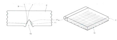
The present patented invention relates to a light guide panel which has a light reflex structure with a micro fluorescent lamp positioned at one side, the light guide panel is characterized in that,
a V-shape groove (10) is formed at a back side of the light guide panel (2) by a diamond cutting machine (hereinafter, referred to as ‘constituent 1’) so as to be narrower as it becomes farther from a fluorescent lamp with a ultra micro tube (hereinafter, referred to as ‘constituent 2’), and
a light-scattering uneven unit (17) is positioned at an inner side of the V-shape grove (10) ((hereinafter, referred to as ‘constituent 3’).
(2) Cited invention 1
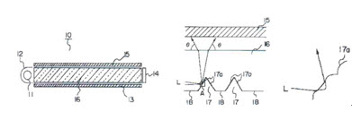
Cited invention 1 relates to a light guide panel (16) having a cold cathode lamp (11). A V-shape groove (17) is formed on a back side of the light guide panel (16) and it is formed to become narrower in interval as it becomes farther from a fluorescent lamp. A micro uneven surface for scattering is formed at a side (17a) of the V-shape groove (17). There are the descriptions, “the micro unevenness surface of the side (17a) of the V-shape groove (17) is formed by a die formed by using a cutting knife blade (31) with roughness at its side” and “when diffused reflection is made by the uneven surface formed at the inner side (17a) of the V-shape groove (17) as in the present invention, the luminance of a front side of the light guide panel is improved, compared with a conventional printing method or injecting method.
(3) Cited invention 2
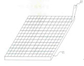
According to a conventional method of manufacturing a light guide panel for a back side illuminant of a liquid crystal display, the light guide panel is manufactured by a method of forming a straight grid in a V shape (V-cutting method) on an acryl surface as a sharp bit (22) straightly and repetitively moves horizontally and vertically on a transparent acryl plate (21), wherein the V-cutting method has the problem in that a lot of time is required to remove acryl particles falling upon the cutting and to process them.
2. Patent Court’s decision (2005HEO10831)
Constituent 1 corresponds to the V-cutting method of cited invention 2, the conventional method of manufacturing a light guide panel for a back side illuminant, in which the sharp bit (22) repetitively moves horizontally and vertically on the transparent acryl plate (21), thereby forming the straight grid in the V shape on the acryl surface. Therefore, even though the specification of the present patented invention is reviewed, the aforementioned special reasons are not approved. Consecutively, the V-shape groove of the light guide panel produced in the aforementioned manner is not considered as being different from the V-shape straight grid of cited invention 2 in terms of the constitution. Constituents 2 and 3 are the same as the constitution that “the V-shape groove is formed to become narrower in interval as it becomes farther from the florescent lamp, and the ultra uneven surface for scattering is formed on the side (17a) of the V-shape groove. The effects of the present invention can be generally predicted from the combination of the aforementioned constituents.
3. Supreme Court’s decision (2006HU3472)
The claims regarding an invention for a product shall be described in the manner of directly specifying the constitution of the product being subjected to the invention, unless there are any special reasons. Even if a method of manufacturing a product is described in the claims of an invention for the product, unless there are any special reasons that the product cannot help being specified only by the method of manufacturing the product , whether the patent invention has any inventive steps shall be determined by comparing the invention specified as the product described in the claims with an invention publicly known before the filing of an application of the invention, without considering the method of manufacturing the product itself.
In claim 1, the preamble portion which describes the publicly known art of the invention is the phrase ‘a light guide panel which has a light reflex structure with a micro fluorescent lamp positioned at one side’. A preceding portion of the rest is related to a method of manufacturing the V-shape groove which ‘is formed by the diamond cutting machine’. In this regard, any special reasons that the V-shape groove cannot help being specified only by the method of manufacturing the V-shape groove are not disclosed. Therefore, only the V-shape groove obtained by the method of manufacturing the same shall be compared with that of the cited invention, without considering the method thereof. As a result, there are no any particular differences between the V-shape groove of the present invention and that of the cited invention in terms of the constitution.
II. Trial for Invalidation of Patent Registration No. 377314
Patent Court’s Decision No. 2004HEO7005 published on Sep. 30, 2005
Supreme Court’s Decision No. 2005HU3017 published on Jan. 12, 2007
- dismissed
1. Gist of the present patented invention and cited invention
(1) Present patented invention (claim 1)
The present patented invention relates to a method of regenerating waste wax for lost wax casting. The method comprises:
a first purifying process to first remove moisture and impurities included in waste wax, by putting the wax collected from an auto graph of a lost wax casting process in a steam heating/dissolving tank and applying heat to the steam tank;
a second purifying process to secondarily remove the moisture and impurities, by withdrawing the firstly purified waste wax from the steam heating/dissolving tank and storing the first purified waste wax in a thermal tank; and
a filtering process of removing residual impurities, by putting the dissolved wax inside the thermal tank into a stirring/dissolving tank, stirring the wax and passing the stirred wax through a compression filtering machine with a filter.
(2) Cited invention
The cited invention relates to an apparatus for regenerating waste wax for lost wax casting. The apparatus comprises:
a steam heating/dissolving tank (10) to heat waste wax (130) collected from an auto graph of a lost wax casting apparatus, and to first remove moisture and impurities (140) included in the waste wax (130);
a thermal tank (20) to store, for a predetermined time, the waste wax (130) transferred from the steam heating/dissolving tank (10) through a pipe line (70) with a transfer pump (71), and to secondarily remove the moisture and impurities (140);
a stirring/dissolving tank (30) to stir the waste wax (130) transferred from the thermal tank (20) through a pipe line (80) with a transfer pump (81), by using upper and lower stirring blades (121, 122) rotating by a motor (110), and to uniformly maintain the distribution, form and properties of residual impurities remaining in the waste wax (130);
a transfer compression pump (40) installed in a pipe line (90) connecting the stirring/dissolving tank (30) and a filtering machine (60), to forcibly transfer the stirred waste wax (130) to the filter machine (60);
a filter (50) installed in the pipe line (90) between the stirring/dissolving tank (30) and the transfer compression pump (40), to remove the residual impurities remaining in the waste wax (130) as transferred;
a filtering machine (60) to fi
|