I. Trial for Confirmation of Scope of Right of Patent Registration
No. 275005
Patent Court’s Decision No. 2004HEO3997 published on Mar. 24, 2005
Supreme Court’s Decision No. 2005HU1011 published on Feb. 8, 2007
- returned for retrial
1. Gist of the present patented invention and the subject invention for confirmation
(1) Claim 1.
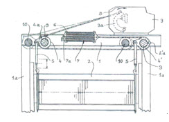
A dobby drawing device in a negative type which includes
a rocking member (3a) for manipulating a heddle frame (2),
a pair of actuating levers (4, 4’) connected to the heddle frame and installed, spaced apart from each other at a predetermined distance,
connection means coupled to the rocking members (3a) and extending over the actuating levers (4, 4’) and to a set of return springs (7) (hereinafter, referred as to ‘preamble constitution’),
wherein the connection means is a single flexible connecting cable (6) including:
a first end fixed to the rocking member (3a),
an intermediate portion directly fixed onto the first lever (4) so as to be guided and to horizontally extend, and fixed onto the second lever (4’) so as to be guided to directly horizontally extend to the set of return springs (7), and
a second end connected to the set of return springs (7).
(2) Gist of the subject invention for confirmation
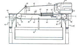
A heddle motion device using a dobby machine (40) in which
a jack lever (41) is connected with one side end of a 1st cable (42),
the 1st cable (42) passes through between a lower guide roller (51) and a upper guide roller (52) positioned in a support frame (50) so that the other end of the 1st cable (42) is connected to a upper fixed ring (32) of a first actuating lever (30),
a 2nd cable (43) is connected between the first actuating lever 930) and second actuating lever (30’), so that both side ends of the 2nd cable (43) are each connected and fixed onto a lower fixed ring (33) of the first actuating lever (30) and a lower fixed ring (33’) of the second actuating lever (30’),
one side end of a 3rd cable (44) is connected with a upper fixed ring (32’) of the second actuating lever (30’) and the other side end of the 3rd cable (44) is connected with one side of a bracket (61) connected with a number of return springs (60), the other side of the bracket (61) is connected with a connection rod (63), wherein the connection rod (63) passes through one side end of a horizontal frame (20) to be fixedly connected by a nut (64),
connection frames (34, 34’) are connected with connection pieces (31, 31’) protruding from the first actuating lever (30) and the second actuating lever (30’), and
a heddle (70) is connected with a lower end of the connection frames (34, 34’) so as to move up/down.
2. Supreme Court’s decision (2005HU1011)
(1) Criteria for determination
Where the subject invention for confirmation uses the patented invention, the subject invention for confirmation is within the scope of the right of the patented invention. However, to establish the relation that the subject invention for confirmation uses the patented invention, the subject invention for confirmation shall add a new technical element to the technical constitution of the patented invention so that the subject invention for confirmation includes all of the gist of the patented invention and uses the same as its, and the patented invention shall maintain the identity of the invention within the subject invention for confirmation. These are the same where the subject invention for confirmation uses not only the same invention as the patented invention but also the equivalent invention to it.
(2) Decision
The present patented invention excludes the use of the guide pulley, or the like, in connecting the rocking member and the first lever by using the cable, whereas the subject invention for confirmation allows the cable to pass through the upper/lower guide rollers (52, 51) in connecting the jack lever (41) and the first actuating lever (30) by the cable (42). In this point, the two inventions differ from each other. The present patented invention has the technical characteristics in that, since the aforementioned cable connection constitution does not have the guide pulley additionally, the structure is simple and the fatigue of the cable is reduced. In the subject invention for confirmation, the cable connection constitution uses the constitution of the support frame (50) including the upper/lower guide rollers (52, 51) performing the same function as the guide pulley between the jack lever (41) and the first actuating lever (30). Therefore, the cable connection constitution according to the present patented invention cannot be considered as maintaining the identity of the invention and being used as it is within the subject invention for confirmation.
II. Trial for Confirmation of Scope of Right of Utility Model Registration
No. 92369
Patent Court’s Decision No. 2005HEO10022 published on Sep. 20, 2006
- finally decided
1. Gist of the present registered device and the subject device for confirmation
(1) Gist of the present registered device (claim 1)
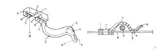
A vine supporting device characterized in that:
a curved elastic part (2) and a side holding part (3) are formed in a single body at one side of a squeezing part (1) (hereinafter, referred to as ‘constituent 1’),
insertion grooves (4, 4’) and formed to be open in the middle of the squeezing part (1) in a direction of a right angle (A) to a direction in which a force applied to the side holding part (3) acts (B) when separating or inserting a vine from or into the supporting device (hereinafter, referred to as ‘constituent 2’),
guide slopes (6, 6’) are formed to be opposite to each other in opening parts (5, 5’) of the insertion grooves (4, 4’), wherein the space of the guide slopes is broad outwardly and narrow inwardly (hereinafter, referred to as ‘constituent 3’),
a concave groove (7) being hollowed inwardly toward the insertion grooves (4, 4’) is formed in the middle of the guide slopes (6, 6’) (hereinafter, referred to as ‘constituent 4’), and
a protruding piece (9) is formed in a curved part (8) (hereinafter, referred to as ‘constituent 5’).
(2) Gist of the subject device for confirmation
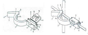
A vine supporting device characterized in that:
a connection part (1), an arch vine supporting part (2) and a handle (3) are formed in a single body,
an insertion groove (4) is formed in the connection part (1), the insertion groove (4) being opened in a right angle direction (B) to a direction of pulling the handle (3) (A) to open the vine supporting part (2),
guide slopes (6) are formed to be opposite to each other in an opening part (5) of the insertion groove (4), the distance between the guide slopes (6) being progressively narrower inwardly, and
a protruding piece (8) is protruded in a bending part (7) between the vine support part (2) and the handle (3).
2. Patent Court’s decision (2005HEO10022)
(1) Criteria for determination
The use relationship in established where the registered device in a subsequently field application adds a new technical element to the technical constitution of a previously registered device, such that the registered device in the subsequently filed application includes all of the gist of the previously registered device and uses the same as it is, and the previously registered device shall maintain the identity of the device within the registered device in the subsequently filed application. These are the same where the registered device in the subsequently filed application uses not only the same device as the previously registered device but also the equivalent device to it.
(2) Constituent 1 of the present registered device
|