Determination of Infringement by Applying Doctrine of Equivalents
I. Trial for Confirmation of Scope of Right of
Patent Registration No. 576078
Patent Court’s Decision No. 2007HEO1008 published on Jun. 22, 2007
- finally decided
1. Gist of the present patented invention and the subject invention for confirmation
(1) Claim 1
A light device for display comprising:
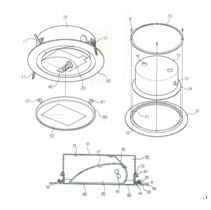
a housing (10) including at least two or more fixing parts (11), a receiving part (12), a fitting part (13) and a outward flange (14), wherein the two or more fixing parts (11) to be fixed onto a panel of the ceiling by the elasticity of a spring are positioned at an outer circumferential surface of the housing (10), the receiving part (12) has an opening inwardly in the housing (10), the fitting part (13) is formed as a portion of the outer circumferential surface is bent outwardly, and the outward flange (14) is positioned at a lower end of the housing (10);
an irradiation unit (20) received in the receiving part (12) inside the housing (10) and including an irradiation side (21) sloped at predetermined angles in an arch shape (hereinafter, referred to as ‘constitution ↘’);
a fixing piece (30) connecting and bolt-fixing the irradiation unit (20) and a bottom surface (15) of the receiving part (12) of the housing (10) receiving the irradiation unit (20) (hereinafter, referred to as ‘constitution ♭’);
a socket unit (40) received in the receiving part (12) and electrically connected thereto;
a light source (41) inserted in the socket unit (40) and positioned at one side in the irradiation unit (20) (hereinafter, referred to as ‘constitution ♩’);
a hollow plate (50) including a mounting part (51) and a protruding part (52), wherein the mounting part (51) to mount the outward flange (14) of the housing (10) is formed at one side of the plate (50) and the protruding part (52) protrudes, along a circumference of the mounting part (51);
a fixing ring (70) placed around the outside of the housing (1) to cover a top of the outward flange (14) of the housing (10) mounted in the mounting part (51) of the plate (50) and fixed onto a top end of the protruding part (52) of the plate (50) by a number of bolts (B) (hereinafter, referred to as ‘constitution ♪’); and
a cover (60) including connection pieces (61) and a penetration part (62) and put into the housing (10) from a lower end of the plate (50), wherein the connection piece (61) protrudes at a side end of the cover (60) and is fitted into and connected with the fitting part (13) formed on the outer circumferential surface of the housing (10) and the penetration part (62) is inwardly installed inside the cover (60) (hereinafter, referred to as ‘constitution ♬’).
(2) Gist of the subject invention for confirmation
A light device for display comprising:
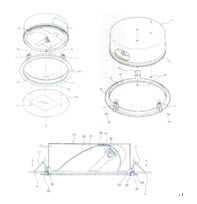
a housing (10) having a receiving part (12) being open downwardly and a bump (14) formed at a lower end of the housing (10);
an irradiation unit (20) having a sloped irradiation side (21) received in the receiving part (12) of the housing (10) and fixed to a fixing piece (30);
a socket unit (40) received in the receiving part (12) and receiving a light source (41);
a ring-shape outer frame (50) including a mounting part (51), a protruding part (52) and a fitting bump (53), wherein the mounting part (51) receives the bump (14) to be mounted, the protruding part (52) extends upwardly toward the outside of the mounting part (51) and the fitting protrusion (53) is formed at the opposite bottom of the mounting part (51);
three elastic clips (11) mounted on to the protruding part (52) of the outer frame (50) and fixed onto the ceiling panel;
a bolt (54) passing through the protruding part (52) of the outer frame (50) horizontally, from its outside to its inside, to control the position of the top of the bump (14) of the housing (10); and
a cover (60) fitted into the fitting protrusion (53) formed at a lower end of the outer frame (50) and screw-connected to a boss part (16) formed at a lower end of the housing (10) by a connection vis (62).
2. Patent Court’s decision (2007HEO1008)
(1) Where the claim(s) of a patented invention describes a plurality of constituents, the technical idea is protected based on the entirety of the interactional relationship of each constituent and each constituent is not independently protected. Thus, where a subject invention for confirmation, to be compared with the patented invention, has only part of the indispensable constituents described in the claims of the patented invention and lacks the other constituents, in principle, the subject invention for confirmation is not within the scope of right of the patented invention. But, even though the subject invention for confirmation includes a substituted or changed part of the constituent of the patented invention, where ↘ the subject invention for confirmation and the patented invention have the common or same technical idea or problem solution principle, ♭ by the substitution, the subject invention for confirmation achieves the same purpose as the patented invention or has substantially the same acting effect, ♩ the substitution is obvious so that it can be easily made by any person skilled in the art at the time of infringement, such as an act of manufacturing a product which is an object of the subject invention for confirmation, ♪ the subject invention for confirmation falls under the so-called public domain which can be easily invented by any person skilled in the art from the already publicly known art or the publicly art at the time of filing an application of the patented invention, or ♬ there is no special reason that the substituted constituent(s) of the subject invention for confirmation is intentionally excluded from the claims through the procedures of filing the application of the patented invention, the substituted constituent of the subject invention for confirmation is considered as having an equivalent relation to the corresponding constituent of the patented invention and therefore it shall be considered as being within the scope of right of the patented invention. Here, the point that the technical idea or problem solution principles are common or the same means that the technical idea or problem solution principles based for the means to solve the specific technical problem raised or unsolved in the conventional art, i.e., the technical characteristic portion of an invention is common or same in the compared inventions. Therefore, in determining the equivalent infringement, the technical idea or problem solution principle shall not overlap with the technical idea or problem solution principle based for the means of solving the problem included in the prior art. Accordingly, in a technical field which includes a lot of the means for solving any technical problems, the commonality or identity of the technical idea or problem solution principle becomes narrower.
(2) In the description of the present invention in claim 1, conventional light devices easily change the direction of light irradiation by using light device covers or special transmission units. However, in the conventional light device, a light device cover is not firmly connected with a light device body, many constituents are needed increasing the production unit price, and the direction of light irradiation is controlled in any one direction only, for example, to the right or left, or upwardly or downwardly, so that the direction of light irradiation is limited in position. To solve these problems of the conventional art, especially, the present invention uses constituent ♪, which is the technical characteristic of the present invention. Many conventional techniques already disclose the constitution in that the constituent corresponding to the housing (10) of
|